Screwdriving
This section describes how to control the screwdriving system using the I/O interface of the SpinBridge.
Definition of TCP positions
During screwdriving, the robot must move to different positions to drive the screw. The axis of the screwdriver must be alligned with the hole in the workpiece. The tool center point is the tip of the bit, and the following positions are defined along the screwdriving path with the bit in the screw:
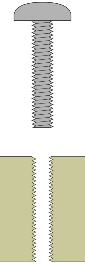
Start: Enter Locate hole step. The screw tip is usually 6 mm above the surface of the workpiece. This distance must match the Start depth parameter in the screw program (note that the value of the insertion depth is negative at this position). The screwdriver is ready to drive the screw.
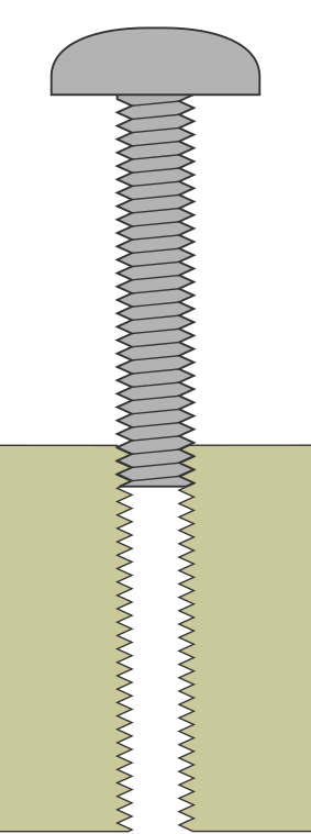
Engaged: Enter Rundown Step. The screw has run 2 mm into the thread. It is time to speed up the screwdriving process.
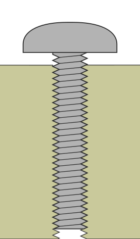
Tighten: Enter Tighten Step. The screwdriver slows down about 4 mm from the seated position, and the screw is driven to the desired torque.
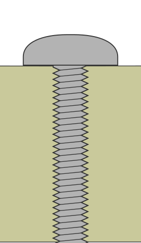
Seated: The screw is seated in the workpiece. The screwdriver has stopped driving the screw.
Tightening - follow screw using speed
Follow this guide to create a collaborative screwdriving sequence, where the robot follows the screw down by setting speeds that matches the screwdriver motor speed and the pitch of the screw. The robot motion must be alligned with the parameters in the screw program for the screw to be driven in correctly and safely. Start by creating a screwdriving program.
Go to Dashboard > Programs > Add new program to create a screwdriving program with parameters that suites the screw and application.
Use the Quick Tightening strategy and select Follow screw using Speed. This will create a three-step screwdriving program with the steps Locate hole, Rundown and Tighten. In each step the robot speed is calculated based on the screwdriver motor speed and the pitch of the screw.
Open the program and check the parameters. In the first step, Locate hole, the Start safety shield must be checked.
Now the program can be mapped to an action in the I/O control. Go to Dashboard > I/O Control > Actions and select the action Start Screw Program.
Create the folowing robot sequence to drive in a screw. It is assumed that a screw is loaded and that the safety shield covers the screw:
Set DI8 high to enable the system.
Wait for DO1 to go high. Now the screw driver is ready.
Move the robot to the Start position.
Set the right combination of DI1-5 to select the tightening program.
Pulse DI6 high to start the screw program.
Move the robot linearly with blend to the Engaged position. The speed of the robot must match the Driving speed parameter in the screw program’s Locate hole step.
Pulse DI7 high to trigger the Rundown step.
Move the robot linearly with blend to the Tighten position. The speed of the robot must match the Driving speed parameter in the screw program’s Rundown step.
Pulse DI7 high to trigger the Tighten step.
Move the robot linearly with blend to the Seated position. The speed of the robot must match the Driving speed parameter in the screw program’s Tighten step.
Wait for either DO4, DO5 or DO6 to go high. This indicates that the screw is done.
Move the robot away.
Tightening - follow screw using force
Follow this guide to create a collaborative tightening sequence, where the robot follows the screw down by putting the robot in force mode with an appropriate force and maximum speed setting. The robot motion must match the the parameters in the screw program for the screw to be driven in correctly and safely. Start by creating a screwdriving program.
Go to Dashboard > Programs > Add new program to create a screwdriving program with parameters that suites the screw and application.
Use the Quick Tightening strategy and select Follow screw using Speed. This will create a three-step screwdriving program with the steps Locate hole, Rundown and Tighten. In each step the robot speed is calculated based on the screwdriver motor speed and the pitch of the screw.
Open the program and check the parameters. In the first step, Locate hole, the Start safety shield must be checked.
Now the program can be mapped to and action in the I/O control. Go to Dashboard > I/O Control > Actions and select the action Start Screw Program.
Note
Although the robot must follow the screw using force, you should select the Follow screw using Speed option in the screwdriving program. The Follow screw using Force option is not supported in I/O control mode, and selecting it will prevent the robot speed from being calculated.
Create the folowing robot sequence to drive in a screw. It is assumed that a screw is loaded and that the safety shield covers the screw:
Set DI8 high to enable the system.
Wait for DO1 to go high.
Move the robot to the Start position.
Set the right combination of DI1-5 to select the tightening program.
Pulse DI6 high to start the screw program.
Put the robot in force mode with a force of 20N in the direction of the screwdriving axis. The maximum speed must be set to the Driving speed parameter in the screw program’s Locate hole step.
When the robot reaches the Engaged position pulse DI7 high to trigger the Rundown step.
When the robot reaches the Tighten position pulse DI7 high to trigger the Tighten step.
Wait for either DO4, DO5 or DO6 to go high. This indicates that the screw is done.
Move the robot away.
Loosening - follow screw using force
Follow this guide to create a collaborative loosening sequence, where the robot follows the screw up by putting the robot in force mode with an appropriate force and maximum speed setting. The robot motion must match the the parameters in the screw program for the screw to be driven in correctly and safely. Start by creating a screwdriving program.
Go to Dashboard > Programs > Add new program to create a screwdriving program with parameters that suites the screw and application.
Use the Loosening strategy and select Follow screw using Speed.
Open the program and check the parameters. In the first step, Locate screw, the Start safety shield must be checked.
Now the program can be mapped to an action in the I/O control. Go to Dashboard > I/O Control > Actions and select the action Start Screw Program.
Note
Although the robot must follow the screw using force, you should select the Follow screw using Speed option in the screwdriving program. The Follow screw using Force option is not supported in I/O control mode, and selecting it will prevent the robot speed from being calculated.
Create the folowing robot sequence to loosen screw:
Set DI8 high to enable the system.
Wait for DO1 to go high.
Move the robot to the Start position.
Set the right combination of DI1-5 to select the loosening program.
Pulse DI6 high to start the screw program.
Put the robot in force mode with a force of 20N in the direction of the screwdriving axis. The maximum speed must be set to the Driving speed parameter in the screw program’s Locate screw step. The tool will go through the Locate screw, Loosen and “Runup”.
When the robot reaches the Engaged position lower the force to 1N and pulse DI7 high to trigger the Exit hole step.
Exit force mode and move the robot to the Start position.
Wait for either DO4, DO5 or DO6 to go high. This indicates that the screw is done.
Move the robot away.
Loading screws
Follow theese steps to create a collaborate loading sequence, where the robot loads a screw into the screwdriver from a screw feeder. The robot motion must match the parameters in the screw program for the screw to be picked up correctly and safely. Start by creating a screwdriving program, that ensures correct movement of the motor as well as the safety shield.
Go to Dashboard > Programs > Add new program to create a screwdriving program just for loading screws. Later we will modify the program to suit a loading sequence.
Use the Drive to depth strategy, a motor speed of 60 RPM, Insertion depth of 0.1 mm (minimum possible) and select Follow screw using Speed.
Open the program and check the parameters.
Change Max program time to 10 s, Reference depth to 0 mm and Initial safety shield position to 0 mm.
In the first step, Locate hole, the Start safety shield must be checked. Driving speed must be changed to 10 mm/s.
Since we only need to pick up the screw, the Rundown and Tighten must be deleted.
Now the program can be mapped to an action in the I/O control. Go to Dashboard > I/O Control > Actions and select the action Start Screw Program with the right program.
Create the folowing robot sequence to load a screw:
Set DI8 high to enable the system.
Wait for DO1 to go high.
Move the robot to the Start position.
Set the right combination of DI1-5 to select the loading program, you just created.
Pulse DI6 high to start the screw program.
Move the robot linearly to the screw in the feeder. The speed of the robot must match the Driving speed parameter in the program’s Locate hole step (10 mm/s).
Pulse DI7 high to trigger to exit the program.
Wait for either DO4, DO5 or DO6 to go high.
Move the robot away.