Understanding Programs
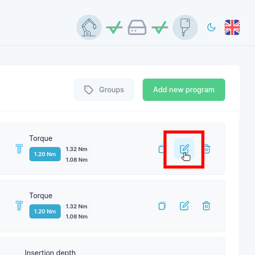
To look at a program, navigate to the programs page and click the View button on the program you wish to view.
General Parameters
You will then be presented with a view that looks like this:
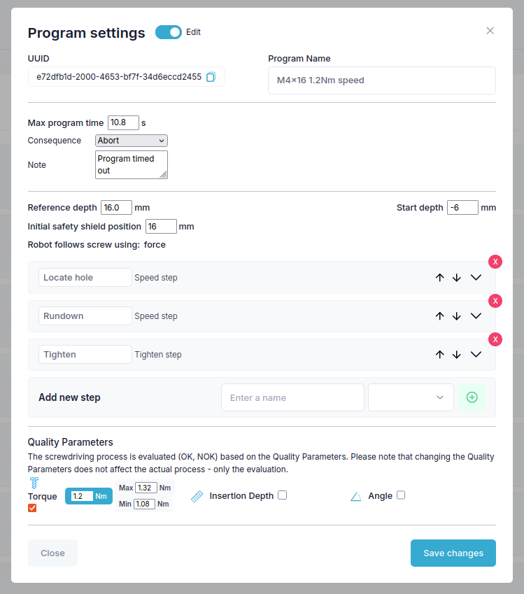
The top of the view shows the name and the uuid of the program, as well as the general program parameters:
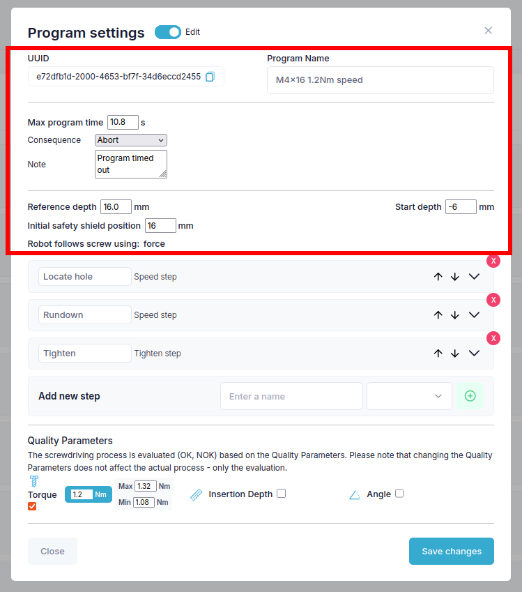
Max program time: is the maximum time the program is allowed to run, if the program is still running after this time the consequence will be triggered.
Consequence: is what will happen if the program runs for longer than the max program time, by default Abort is selected which will stop the program and send the Note as an error message.
Note: is the error message that will be sent if the consequence is triggered.
Reference depth: is the depth that you will be teaching the program at, e.g. with a 16 mm screw fully inserted, the reference depth would be 16 mm.
Start depth: is the depth that the program will start at, so usually -6 mm to start the program with 6 mm between the tip of the screw and the surface of the part.
Follow screw using force/speed: is the method used to follow the screw during the insertion process, either by applying a constant force or by controlling the speed of the tool.
Initial safety shield position: is the position of the safety shield when the program starts, so if you want the safety shield to cover a 16 mm screw, you would set this to 16 mm.
Note
When referring to depth (i.e. Reference depth or Insertion depth), it describes the distance from the tip of the screw to the top of the screw hole, so a 16 mm screw thats fully inserted has a insertion depth of 16mm.
Program Steps
The middle part of the view shows the steps of the programs:
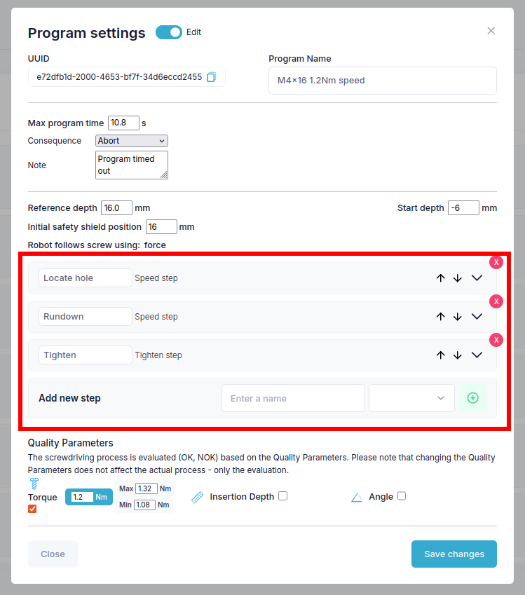
In this program there are 3 steps Locate hole, Rundown and Tighten. Locate hole drives the tool at low RPM util it detects contact with the thread. Then it proceeds to the next step. Rundown drives the tool at a high RPM until it detects that it is near the final insertion depth and then proceeds to the final step. Tighten runs the tool at a low speed until it detects the threshold torque then switches the tool to torque mode to achieve the target torque and then stops the tool.
What is a step?
A step consists of two parts: Parameters to control and Parameters to monitor. Currently you can choose from two step types, Step types are differentiated by the set of Parameters to control they possess:
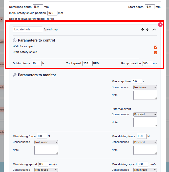
Speed step: is a step that drives the tool at a specific RPM. It has the control parameters: Driving force[N] Tool speed[RPM] and Ramp duration[ms]. The Ramp duration is the time the tool attempts to take to ramp to the specified tool speed, the Wait for ramped option will wait for the ramp to finish before starting to monitor the processors. Finally the start safety shield option will set the safety shield to hold its position until the end of the program.
Tighten step: drives the tool at a specific RPM until a set torque threshold. Then it switches to torque mode and tightens to the specified target torque and stops the tool. It has the same parameters as the speed step but also has the parameters: Torque goal[Nm] and Torque threshold[Nm]. The Torque threshold is the torque that the tool will switch to torque mode at and the Torque goal is the torque that the tool will tighten to in torque mode, when the tool reaches the torque goal it will stop the tool and put the Screw motor in the state Idle, this can be monitored by the Parameters to monitor.
This is the Locate hole step(Speed step) of the M4x16 1.2Nm speed program:
What are Parameters to monitor?
The Parameters to monitor are the set of parameters that will determine the program flow, each parameter has a value, a consequence and a note. The consequence is what will happen if the value is reached. At the moment only the Abort and Proceed consequences are fully implemented. The Abort consequence will stop the program and send the note as an error message, and the Proceed consequence will proceed to the next step. The rest of the options will at the moment be ignored. By default the consequence is set to Not in use which will completely ignore the parameter.
Abort: will stop the program and send the note as an error message.
Proceed: will proceed to the next step.
Not in use: will completely ignore the processor.
The monitor types are:
Max step time: is the maximum time the step is allowed to run, if the step is still running after this time the consequence will be triggered.
Min/Max driving force: is the downwards load on the screw exerted by the tool, if the force is reached the consequence will be triggered.
Min/Max insertion depth: is the depth that the screw is inserted, if the depth is reached the consequence will be triggered.
Min/Max tool speed: is the speed of the tool, if the speed is reached the consequence will be triggered.
Min/Max torque: is the torque of the tool, if the torque is reached the consequence will be triggered.
Min/Max angle: is the angle of the tool measured from when the screw program started, if the angle is reached the consequence will be triggered.
Screw motor state: is the state of the screw motor, if the state is reached the consequence will be triggered. this is used in the Tighten step to monitor if the motor is idle, indicating that the torque ramp is done.
These are the Processors of the Locate hole step:
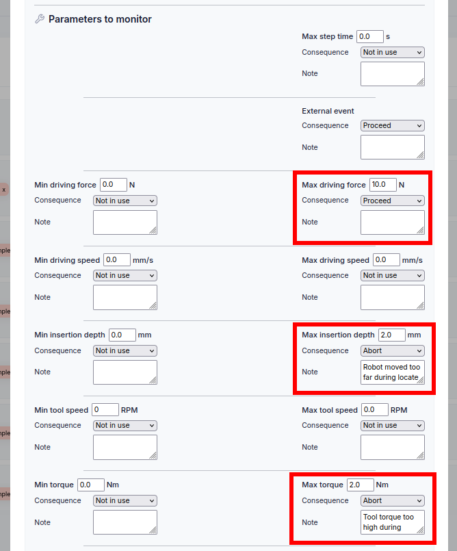
The goal of these processors are as follows:
Max driving force: is used to detect when the tool is in contact with the thread, and will proceed to the next step when the force is reached.
Max insertion depth: is used as error detection, if the tool is not in contact with the thread when this depth is reached, the program will stop.
Max torque: is used as error detection, the tool should be free spinning so if the torque is above the value the program will stop.
Quality Parameters
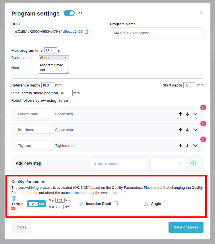
The screwdriving process is evaluated OK or NOT OK against the quality parameters. Please note that changing the Quality Parameters does not affect the actual process, it only affects the evaluation of the process.
Torque: is the overall torque target. The actual torque target that the system is aiming to achieve is set by the final tighten program step.
Min/Max are the goal values that the result is evaluated against, if the torque achieved is within the min/max values the program is considered OK otherwise it is considered NOT OK.
Insertion depth: is the overall insertion depth target. The actual insertion depth target that the system is aiming to achieve is set by the final program step.
Min/Max are the goal values that the result is evaluated against, if the insertion depth achieved is within the min/max values the program is considered a OK otherwise it is considered NOT OK.
Angle: is the overall angle target. The actual angle target that the system is aiming to achieve is set by the final program step.
Min/Max are the goal values that the result is evaluated against, if the angle achieved is within the min/max values the program is considered OK otherwise it is considered NOT OK.