Dashboard
If I/O Control is enabled on the SpinBridge, the dashboard can be used to monitor the digital inputs and outputs and to map configurable actions to the digital inputs.
Overview tab

Overview tab
The Overview tab shows the current state of the digital inputs and outputs.
Actions tab
Actions tab
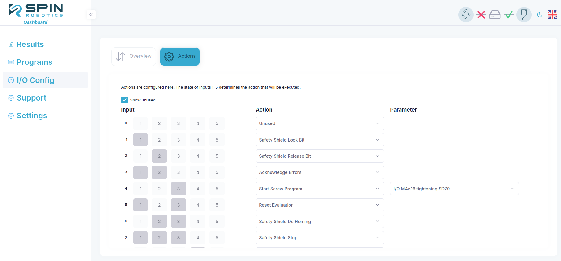
The Actions tab allows you to map configurable actions to the digital inputs. By combining digital inputs 1 to 5, you can map up to 32 different actions, some with configurable parameters.
Hint
The first column shows the decimal value of the configurable digital inputs, with DI1 as the least significant bit and DI5 as the most significant bit. This enables you to calculate the binary value of the digital inputs. E.g. if the decimal value is 5 = 0b00101, DI1 and DI3 should be set high to trigger the action.
Some actions takes parameters, which can be set in the Parameters column. In case of a Start Screw Program action, the desired screw program can be selected in the parameters column. Any program defined via the Dashboard > Programs menu can be selected.