System Overview
A screwdriving system is built from four parts.
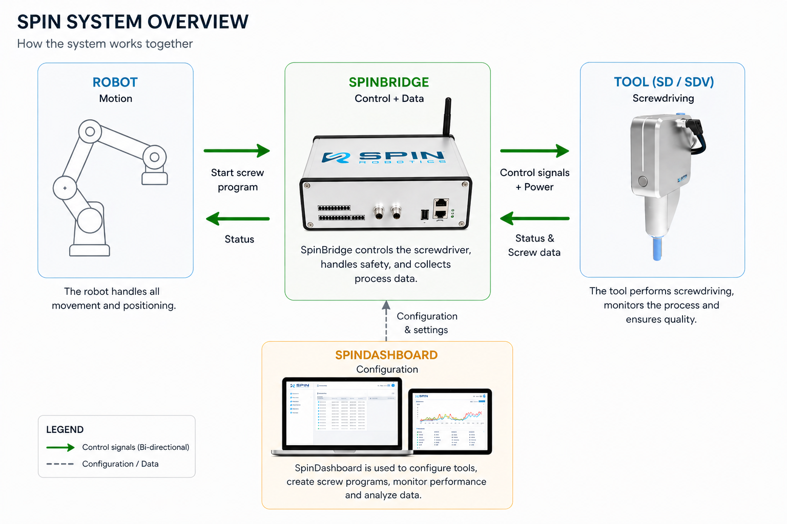
The robot moves the tool; the Spin Bridge drives the screw.
Robot — moves the tool to the screw and starts a screw program. It does no screwdriving of its own.
Tool — turns the screw, and measures torque, angle and depth while it turns.
Spin Bridge — powers and controls the tool, runs the screw program and stores the result. It is the part the robot talks to.
Spin Dashboard — the web interface of the Spin Bridge, where screw programs are written and results are inspected.
That split decides where to look when something is wrong: a screw tightened to the wrong torque is a screw program question, answered in the Spin Dashboard; a tool that arrives at the wrong place is a robot program question.
The Tool
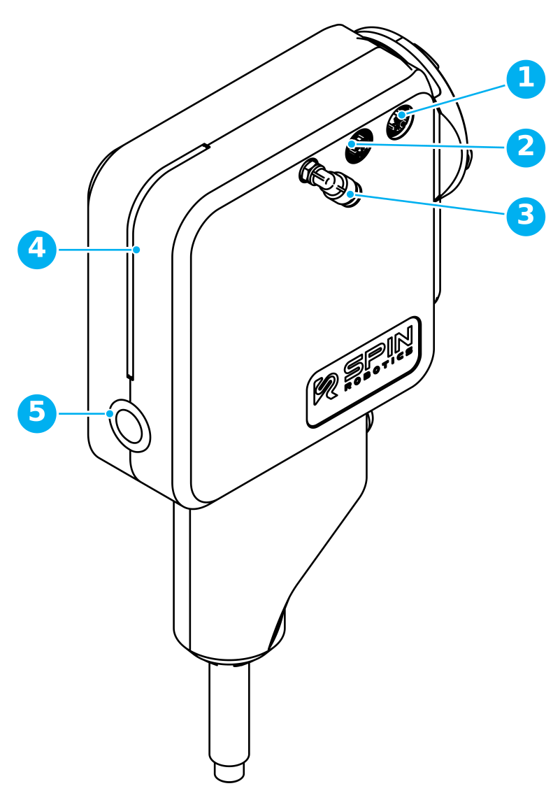
Communication cable connector — everything the Spin Bridge and the tool say to each other.
Power cable connector — the motor supply from the Spin Bridge.
Vacuum connector — on SDV tools only. The tool does not generate vacuum; it is supplied externally.
LED strip — shows what the tool is doing.
Front button — triggers whatever action it has been mapped to.
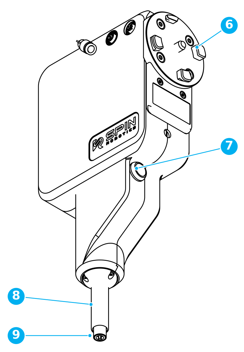
Spin Mount — holds the tool on the robot flange. It stays on the robot; the tool twists in and out of it by hand.
Freedrive button — for guiding the robot by hand while teaching a position.
Safety shield — covers the bit and the screw, and retracts as the screw goes in.
Bit and bit collar — the bit turns the screw; the collar around it holds the screw while the robot carries it.
The tool rests on a linear rail. A force pushing it upward displaces it, and the safety sensor then stops the robot and disables the tool.
The Spin Bridge
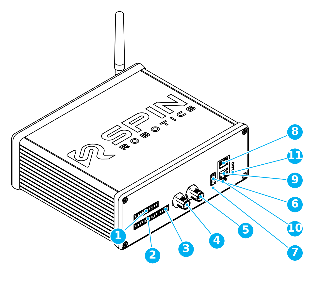
Digital outputs — eight, numbered 1 to 8.
Digital inputs — eight, numbered 1 to 8.
Safety connector — carries the tool’s safety signal to the robot or PLC.
Tool power cable connector — marked Power.
Tool communication cable connector — marked Comm.
USB port
Factory reset button
1 Ext. network — the ethernet port the Spin Dashboard is reached on.
2 Robot — the ethernet port for the robot.
USB micro port — for service use only.
Status LEDs — Power, Tool and Robot.
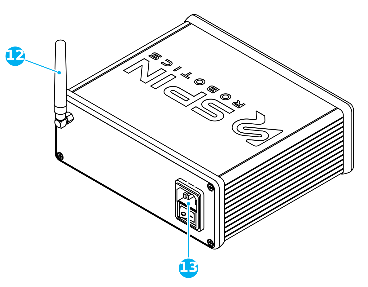
Wi-Fi antenna
AC connector and ON/OFF switch
The digital I/O both controls the tool without a plugin and reports its state.
SD vs SDV Series
Four models cover the torque range: SD35, SD50, SD70 and SD120. They differ in torque and speed, not in how they are set up or programmed.
Screws are picked up magnetically as standard, with a magnetic bit collar. An SDV tool is the same tool with the vacuum option: a vacuum port, and a vacuum bit collar and mouthpiece that hold the screw by suction instead. Vacuum pickup is what non-magnetic screws — stainless steel, brass, plastic — require. The tool does not generate vacuum; it is supplied externally.