Installing and Connecting the Tool
Mount the Spin Mount
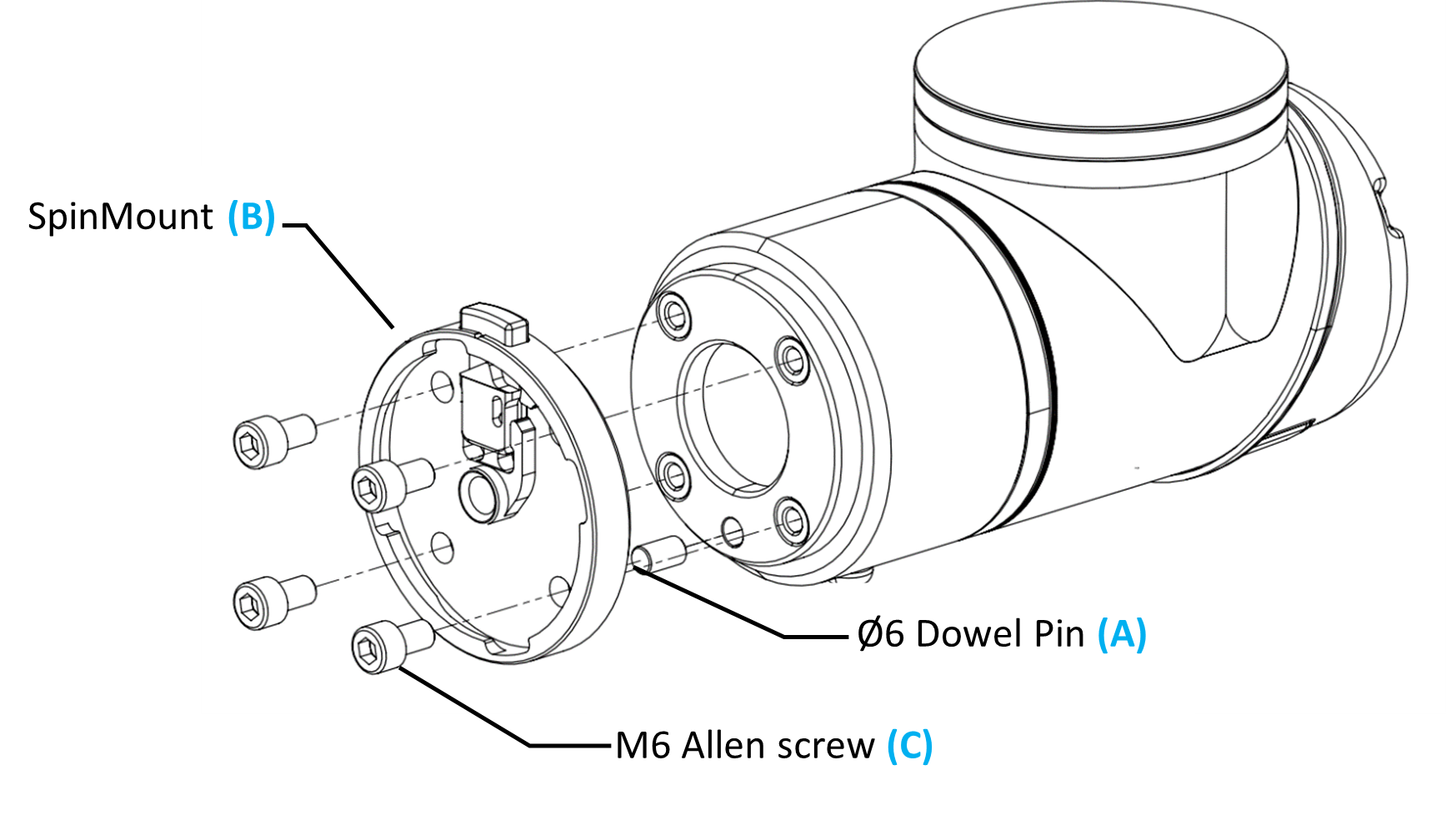
Insert the dowel pin (A) into the robot flange.
Fit the Spin Mount (B) and fasten it with the M6 screws (C), tightened to the robot manufacturer’s specification.
Note
Always fit the dowel pin. Without it the tool’s orientation will be wrong and the preconfigured TCP will not match.
Mount the Tool
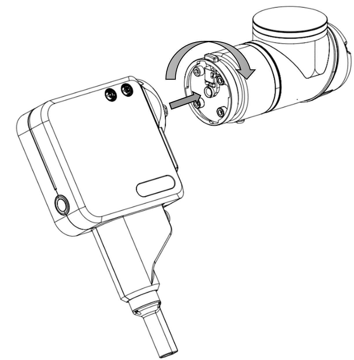
Push the tool into the Spin Mount and turn it clockwise until it clicks.
Check that the tool is fully locked. A loose tool causes unstable screwdriving.
Connect the Tool Cables
Connect the M12 4-pin power cable to the power connector (D) on the tool, and the M12 8-pin communication cable to the communication connector (E).
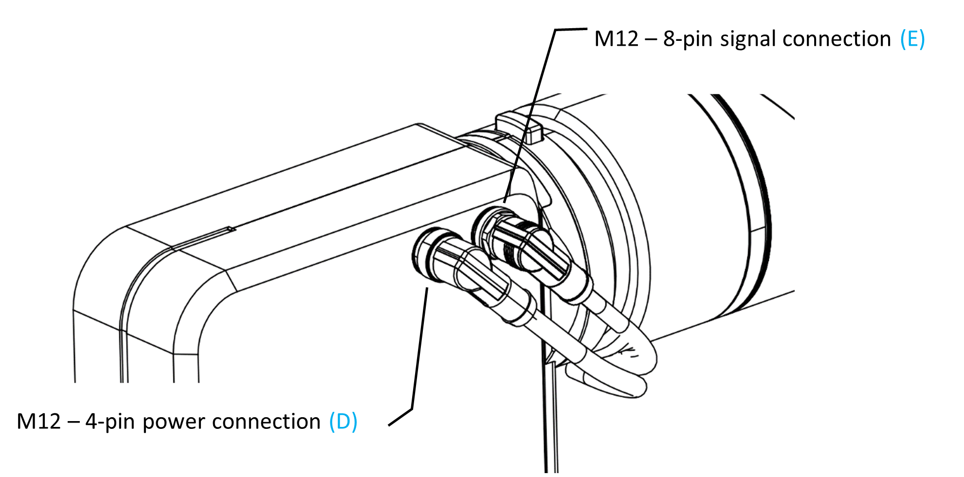
Run both cables along the robot arm and fasten them with Velcro straps, leaving enough slack at each joint.
Notice
Straps pulled too tight can damage the cables as the robot moves. Keep them snug but not tight.
Place and Connect the Spin Bridge
Place the Spin Bridge near the robot controller.
Connect the tool’s power cable to Power (F) and its communication cable to Comm (G).
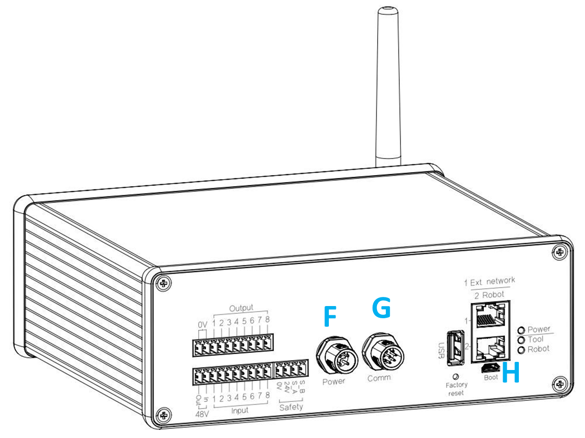
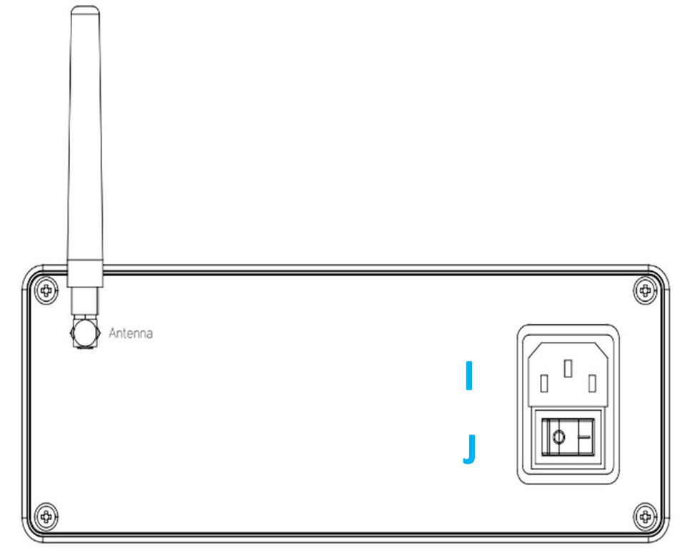
Fit the antenna and connect the AC power cable (I).