Connecting the Spin Bridge to the Robot
Universal Robots and Kassow Robots connect to the Spin Bridge over ethernet. Any other robot or a PLC connects over the Spin Bridge’s digital I/O. The two cannot be combined: with a UR or Kassow connected over ethernet, the I/O cannot be used.
Connect Ethernet or I/O
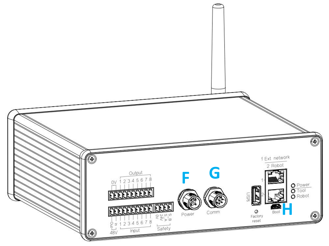
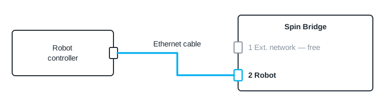
Directly to 2 Robot — recommended. Run an ethernet cable from the controller to 2 Robot (H). The port has a fixed address, so nothing needs setting on the Spin Bridge; the robot’s address is set as described in Set the Robot’s Network Address.
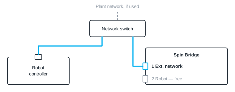
Through a network switch. Connect the controller and 1 Ext. network to the same switch. 1 Ext. network then takes either a static address in the plant’s subnet or one from the plant’s DHCP server. Set it as described in 1 Ext. network, and the robot’s address as described in Set the Robot’s Network Address.
Directly to 2 Robot — recommended. Run an ethernet cable from the controller to 2 Robot (H). The port has a fixed address, so nothing needs setting on the Spin Bridge; the robot’s address is set as described in Set the Robot’s Network Address.
Through a network switch. Connect the controller and 1 Ext. network to the same switch. 1 Ext. network then takes either a static address in the plant’s subnet or one from the plant’s DHCP server. Set it as described in 1 Ext. network, and the robot’s address as described in Set the Robot’s Network Address.
Wire the robot’s or PLC’s digital outputs to the Spin Bridge’s Input terminals, and its digital inputs to the Output terminals. The I/O terminals are powered with the robot’s 24 V and 0 V through the safety terminals, which the next section connects.
As an example, a Fanuc CRX is wired like this:
Spin Bridge |
Fanuc CRX |
|---|---|
Input 1–8 |
Digital outputs 101–108 |
Output 1–6 |
Digital inputs 101–106 |
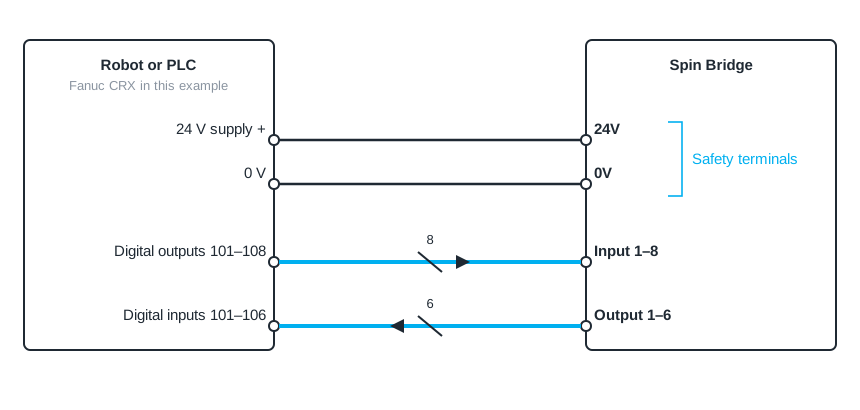
The robot supplies the I/O through the safety terminals, so the robot’s 24 V and 0 V are the reference for every I/O signal.
Notice
Wiring the I/O terminals while the robot or the Spin Bridge is powered can damage the equipment. Switch both off first.
Connect the Safety Signal
The supplied safety cable carries the tool’s safety signal to the robot and the robot’s 24 V supply to the Spin Bridge. The Spin Bridge prints its four safety terminals 0V, 24V, S_b (OSSD B) and S_a (OSSD A), and the steps below name each wire by its terminal.
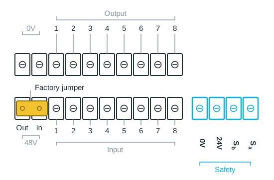
The safety terminals, and the factory jumper that closes the 48 V motor supply.
Connect the safety cable to the Safety terminals.
Connect its wires at the robot:
S_a and S_b to the emergency-stop inputs EI0 and EI1 on the control box’s Safety terminals. Universal Robots accept OSSD signals directly. In an advanced integration, the safeguard-stop inputs SI0 and SI1 can be used instead.
24V and 0V to the same terminals on the control box’s Power block.
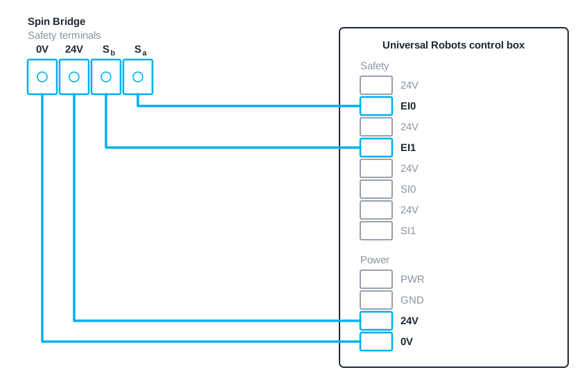
The emergency-stop terminals are interleaved with 24 V pins that stay unused.
Kassow robots do not accept OSSD signals directly, so a safety relay converts them.
S_a and S_b to the safety relay, and the relay’s outputs to the robot’s emergency-stop input.
24V and 0V to the robot’s 24 V supply.

The safety relay converts the OSSD signals from the Spin Bridge.
S_a and S_b to the robot’s or PLC’s emergency-stop input if it accepts OSSD signals, or otherwise to a safety relay that converts them.
24V and 0V to the robot’s or PLC’s 24 V supply.
Warning
Without the safety cable, the robot does not stop when the tool’s safety sensor triggers. Do not operate the system in a collaborative application without it.
The jumper between the 48V terminals closes the tool’s motor supply on delivery. It stays in place unless a safety relay is to interrupt that supply; see 48 V Motor Supply.
Wire the Tool Buttons
The tool’s freedrive and front buttons reach the robot through the control box’s configurable I/O.
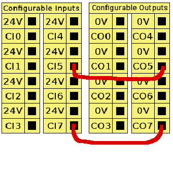
The configurable I/O connector in the UR control box.
Power off the robot.
Open the control box.
Fit jumper wires from CI5 to CO5 and from CI7 to CO7, as in the figure.
Power on the robot.
A Kassow robot is guided by hand with the backdrive button on its wrist or on the teach pendant, so the freedrive button needs no wiring.
Wire Output 2, which reports the freedrive button, to a robot input.
Power On and Check the Safety Stop
Switch on the Spin Bridge with the power switch (J).
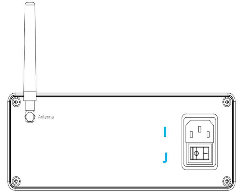
With the robot powered on, push the tool upward to trigger the safety sensor, and check that the robot stops.
Warning
If the robot does not stop, the safety function is not working. Do not operate the system; check the wiring and the safety configuration.
This check does not replace the validation described in Verification and Operation.