Installing and Configuring a Vacuum System
The tool does not generate vacuum. The integrator supplies it with a vacuum pump or a vacuum generator such as a venturi, dimensions the supply for the application, routes the tubing clear of the robot’s motion, switches the vacuum from their own robot program through a robot output, and validates the result in the final application.
Note
Vacuum needs a tool with the vacuum option. Any current tool can take it, but older tool models cannot. The mouthpieces and the M5 push-in fitting come with the option.
Vacuum Supply Requirements
The vacuum at the tool port has to be continuous and reach at least 60 % (about -600 mbar). The tool is not airtight, so the supply has to keep generating vacuum through pickup and transport, making up for leakage.
The level needed in practice depends on the screw — its size, weight, head shape, material and surface finish — on how fast and in which orientation it is carried, and on the whole pneumatic system: tubing length and diameter, fittings, leaks and the vacuum generator. With too little vacuum, screws are not picked up or are dropped on the way, which costs reliability and cycle time.
Connect the Vacuum Supply
Connect the vacuum supply to the tool’s M5 push-in fitting with 6 mm OD polyurethane (PU) or polyamide (PA) tubing.
Push the tubing in until it seats. Tubing that is not fully inserted is a common cause of leaks and weak vacuum.
To disconnect the tubing, press the collet ring on the fitting and pull the tube out.
Install the Vacuum Sensor
The vacuum sensor lets the robot program check that a screw has been picked up and is still held on the way to the hole. The Festo SPAN-V1R-Q4-PNLK-PNVBA-L1 comes with the vacuum option. Another sensor can be used, but this is the one Spin Robotics recommends: it covers the full range from 0 to -1 bar and offers Auto Difference Monitoring, which adapts to the operating vacuum and detects the drop caused by a leak or a lost screw.
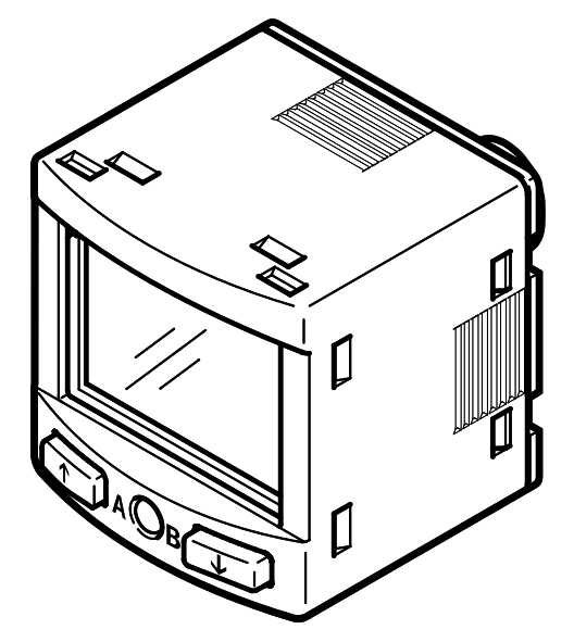
Key specifications
Parameter |
Value |
|---|---|
Measuring range |
0 … -1000 mbar |
Supply voltage |
15 … 30 V DC (24 V rated) |
Switching outputs |
2× PNP (or NPN) |
Switching functions |
Threshold, Window, Auto Difference Monitoring |
Switch-on/off time |
Typical 2 ms |
Protection class |
IP40 |
Connector |
4-pin, L1 |
Mount the sensor in the vacuum supply line, as close to the tool as practical: the less tubing between them, the faster it responds to a leak at the tool tip.
Wiring
Pin |
Wire color |
Signal |
Function |
|---|---|---|---|
1 |
Brown (BN) |
+24 V |
Supply voltage |
2 |
Black (BK) |
OutA |
Switching output → connect to robot digital input |
3 |
White (WH) |
OutB |
Analog / second output — not used |
4 |
Blue (BU) |
0 V |
Supply reference |
Connect +24 V (pin 1, brown) and 0 V (pin 4, blue) to the robot’s or an external 24 V supply, and OutA (pin 2, black) to a digital input:
Any digital input. It is selected as the Sensor input of the Pick screw node; see Loading Screws.
Any digital input. Load Screw waits on a numeric variable, its Wait Condition; see Loading Screws.
An input that the robot’s or PLC’s program reads; see Loading Screws.
Note
The sensor’s 0 V has to be shared with the 0 V of the robot’s or PLC’s digital inputs. Without the common reference, the output switches unreliably or not at all.
Configure the Sensor
Change the display unit to mbar first, then set up Auto Difference Monitoring or a fixed threshold. For commissioning, TEACH mode and IO-Link, see the Festo SPAN operating instructions (document 8225842).
Change the Display Unit
The sensor ships set to bar. Change it to mbar, so that the display and the settings below use the same unit as this manual.
Ensure the sensor is powered and in RUN mode (pressure value displayed).
Press [Edit] briefly → Edit appears, OutA flashes.
Use [A] or [B] to navigate to Spec → Spec flashes.
Press [Edit] briefly → Filt flashes (first item in the Spec menu).
Press [Edit] briefly to accept the current Filt value and advance → Unit flashes.
Use [A] or [B] to select mbar.
Press [Edit] to confirm.
Press and hold [Edit] for 3 seconds to return to RUN mode.
The display then shows vacuum in mbar, such as -650 for -650 mbar, and SP.Lo, SP.Hi and d.SP are entered in mbar too.
Set Up Auto Difference Monitoring
Auto Difference Monitoring learns the stable vacuum level after a screw is picked up, and switches the output off if the vacuum then drops, for example because the screw has fallen off the bit. Because it adapts to the actual operating level, it copes with variation in the vacuum source, the tubing length and the screw geometry without recalibration.
How it works
When vacuum is activated and the pressure enters the valid range (between SP.Lo and SP.Hi), the sensor observes the signal for a configurable averaging period (t.obS).
At the end of the observation period, the average pressure is stored as the reference value (PRef). The switching output activates to indicate that vacuum is established.
During transport, the sensor monitors the vacuum level continuously. If the pressure deviates from PRef by more than the differential threshold (d.SP), the output switches off — indicating leakage or a dropped screw.
Configuration parameters
Parameter |
Description |
Recommended value |
|---|---|---|
SP.Lo |
Low absolute vacuum bound (less vacuum) |
-550 mbar |
SP.Hi |
High absolute vacuum bound (more vacuum) |
-750 mbar |
t.obS |
Observation time for averaging (ms) |
200 – 500 ms |
d.SP |
Differential threshold: deviation from PRef that triggers a fault |
50 – 100 mbar |
LOGC |
Output logic |
NO (normally open) |
Hint
The recommended values above are starting points. Validate and adjust based on the actual vacuum level in your application. SP.Lo is the lower absolute vacuum value (less negative, e.g., -550 mbar) and SP.Hi is the higher absolute vacuum value (more negative, e.g., -750 mbar). For a system running at -650 mbar, set SP.Lo below and SP.Hi above that operating point. Increase d.SP if the system produces false faults during normal operation. Decrease d.SP for higher sensitivity to leakage.
Configuration procedure
Ensure the sensor is powered and in RUN mode (pressure value displayed).
Press [Edit] briefly → Edit appears, OutA flashes.
Press [Edit] briefly → Fctn flashes.
Use [A] or [B] to select
d_|‾|_(Auto difference monitor function).Press [Edit] to confirm → first parameter (SP.Lo) is displayed.
Set SP.Lo using [A] / [B], then press [Edit] to confirm.
Set SP.Hi using [A] / [B], then press [Edit] to confirm.
Set t.obS (observation time in ms) and confirm with [Edit].
Set d.SP (differential threshold) and confirm with [Edit].
Set LOGC to NO (output active when vacuum stable) and confirm.
Press and hold [Edit] for 3 seconds → sensor returns to RUN mode.
Fixed-Threshold Monitoring
The simpler alternative is a single switching point below the operating vacuum, for example -500 mbar for a system running at -650 mbar.
Hint
Fixed-threshold monitoring has two limits. It does not distinguish between a screw that is present but held weakly and one that is missing entirely, and it reports false negatives when the bit sits tightly inside the screw socket — the screw is held correctly, but vacuum reads low for unrelated reasons. For high-reliability applications use Auto Difference Monitoring instead, or add an optical sensor for independent confirmation of screw presence.