Configuring the Robot
Install the Plugin
Download the latest URCap and copy it to a USB stick.
Insert the USB stick into the teach pendant.
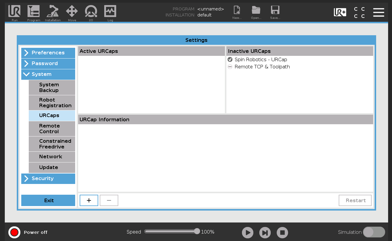
From the Menu button, select Settings / System / URCaps and press +.
Select the URCap file on the USB stick and press Open.
Press Restart to restart the robot.
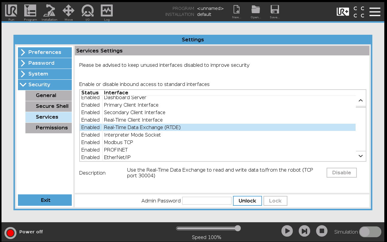
Under Settings / Security / Services, check that Real-Time Data Exchange (RTDE) is enabled. The Spin Bridge communicates with the robot over RTDE.
The Spin Robotics CBun needs Kassow Robots’ Kord CBun (Kassow Open Realtime Data), in the version that matches it.
Download the latest Spin Robotics CBun and the Kord CBun that goes with it, and copy both to a USB drive.
Insert the USB drive into the robot controller.
From the menu
 on the teach pendant, select Settings / CBuns.
Remove any installed Kord CBun: select it and press -.
Press + to install the Kord CBun from the USB drive, select Kassow Open Realtime Data in the list, and press the other + to its right.
Repeat steps 3–5 for the Spin Robotics CBun.
On the Workcell tab, check that the custom devices KORD_UDP and SPIN are both present.
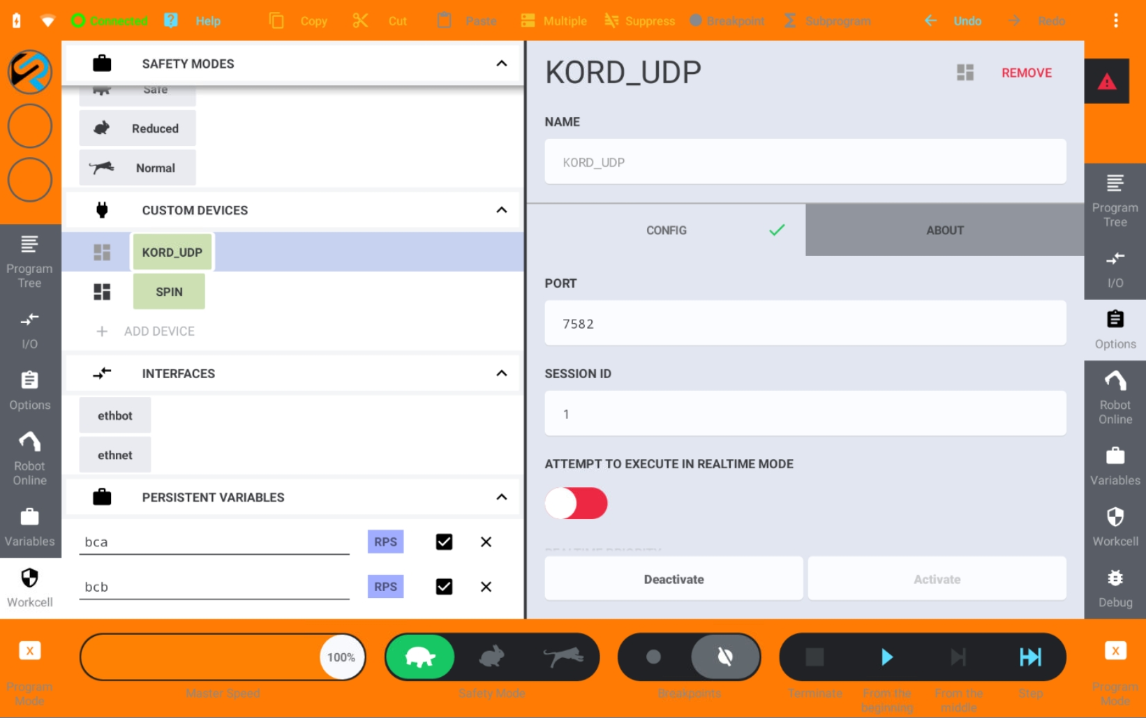
Select Workcell / Custom Devices / KORD_UDP and press Activate.
No plugin is needed.
Set the Robot’s Network Address
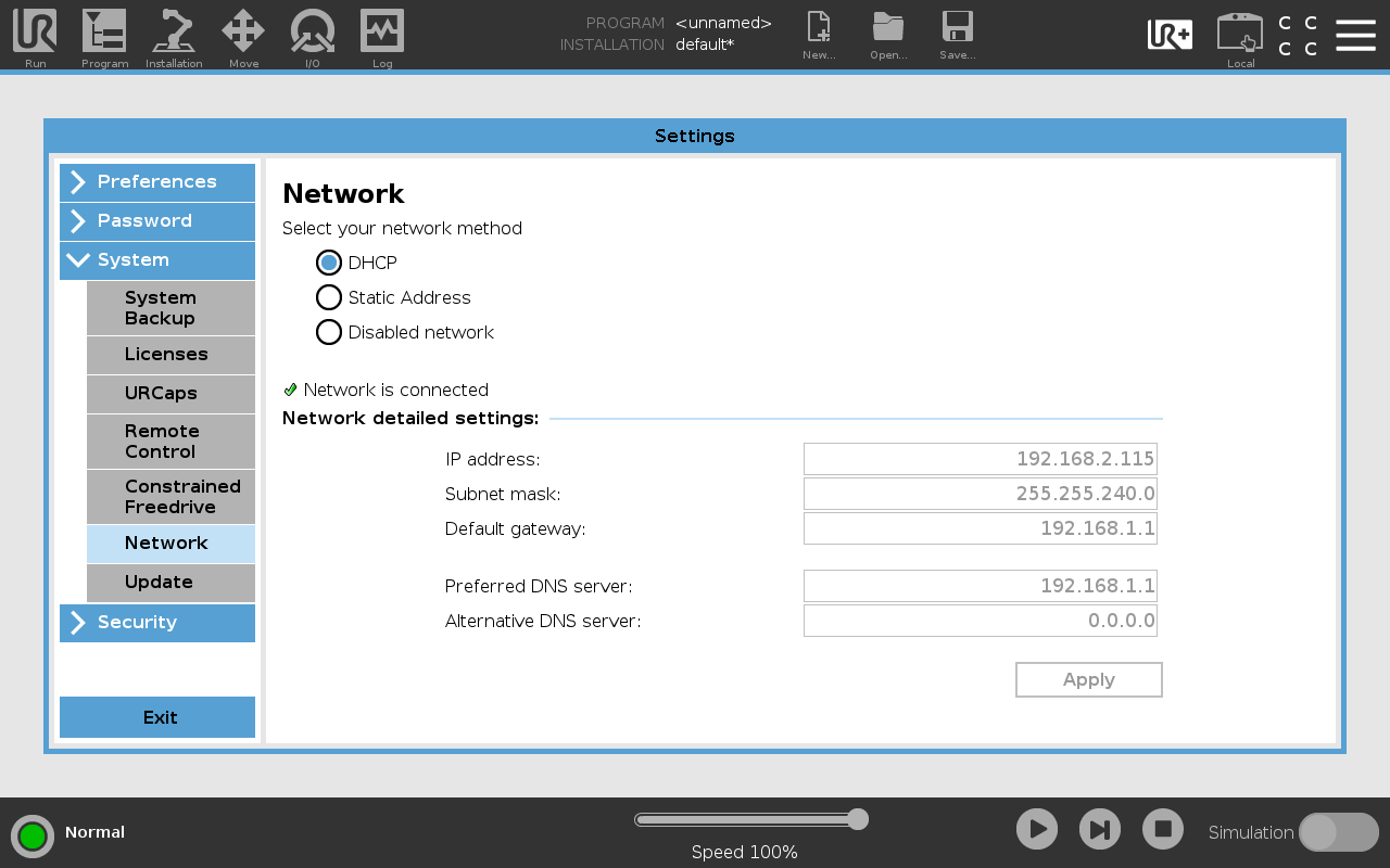
The address is set under Settings / System / Network, for the topology chosen in Connect Ethernet or I/O. Press Apply to save it.
Directly to 2 Robot. Select Static Address, and enter an IP address from 192.168.37.2 to 192.168.37.254, such as 192.168.37.100, with subnet mask 255.255.255.0. Leave the default gateway and both DNS servers at 0.0.0.0.
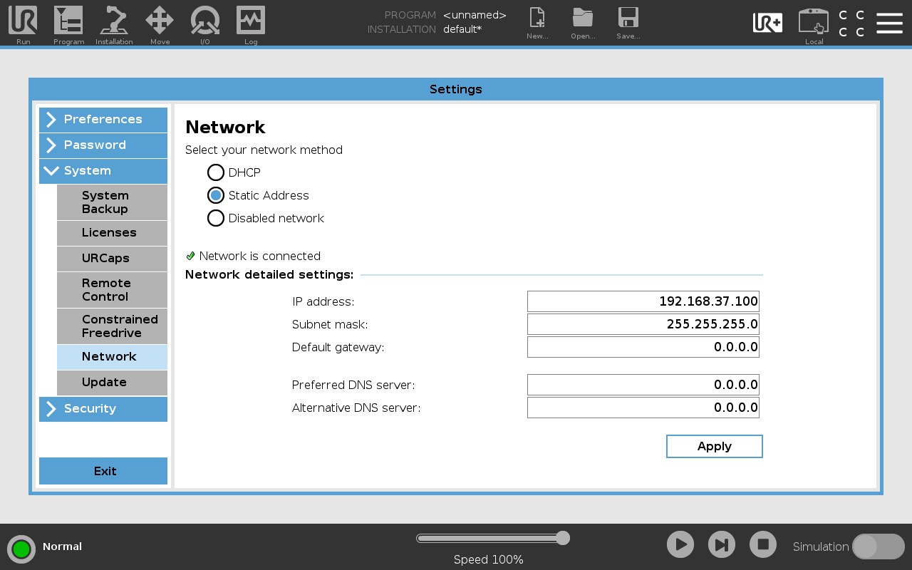
Through a switch, with static addresses. Select Static Address, and enter an IP address and subnet mask in the same subnet as 1 Ext. network.
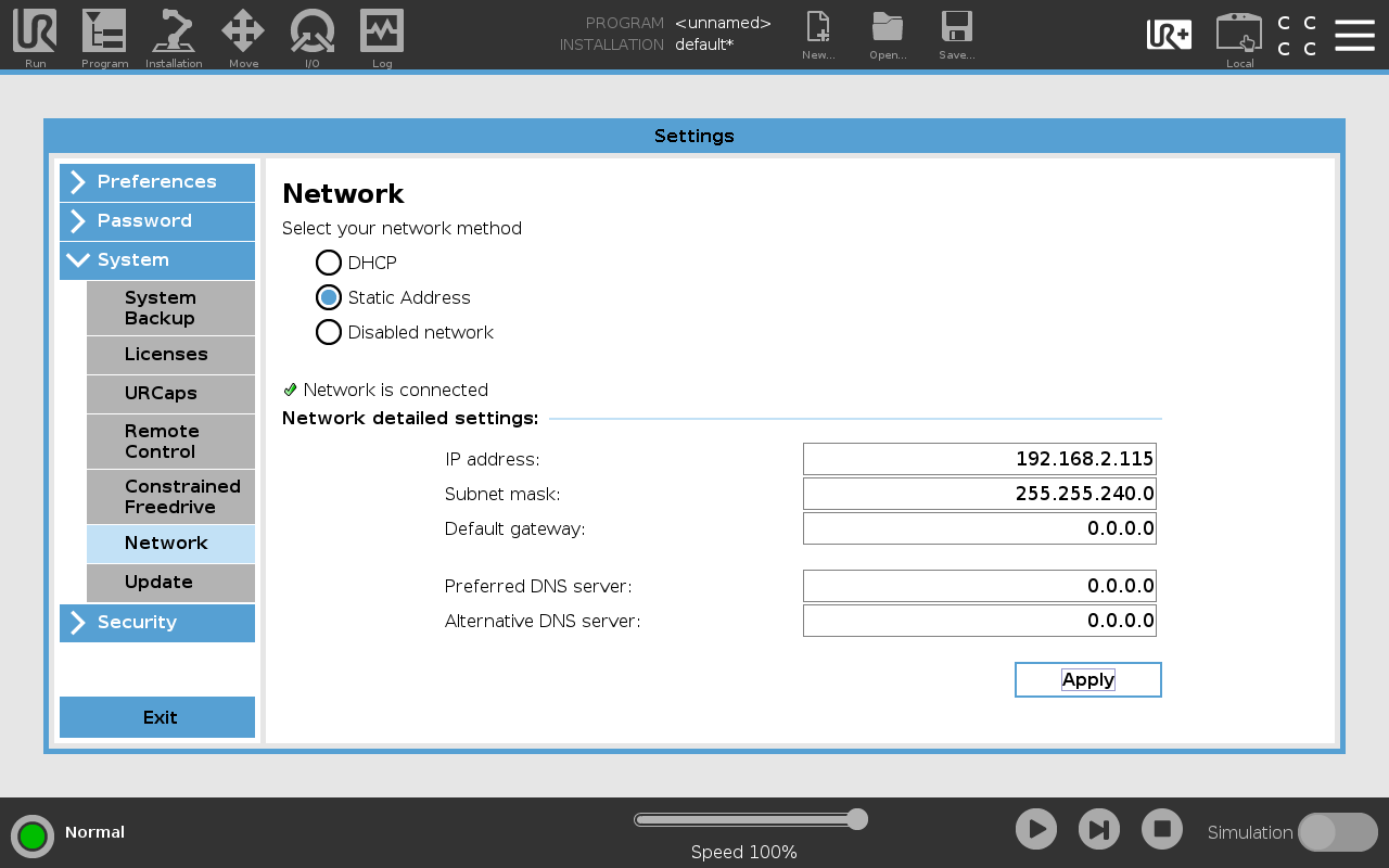
Through a switch, with DHCP. Select DHCP.
The address is set under Workcell / Interfaces / ethnet, for the topology chosen in Connect Ethernet or I/O.
Directly to 2 Robot. Select Static IP, and enter an IP address from 192.168.37.2 to 192.168.37.254, such as 192.168.37.100, with netmask 255.255.255.0.
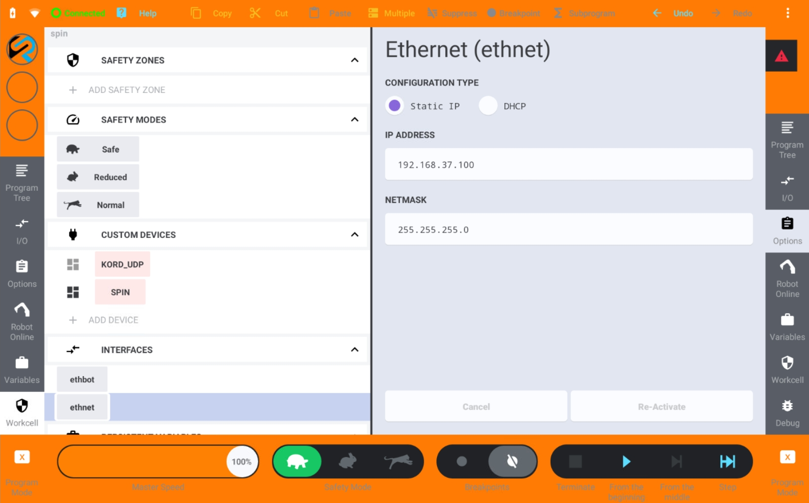
Through a switch, with static addresses. Select Static IP, and enter an IP address and netmask in the same subnet as 1 Ext. network.
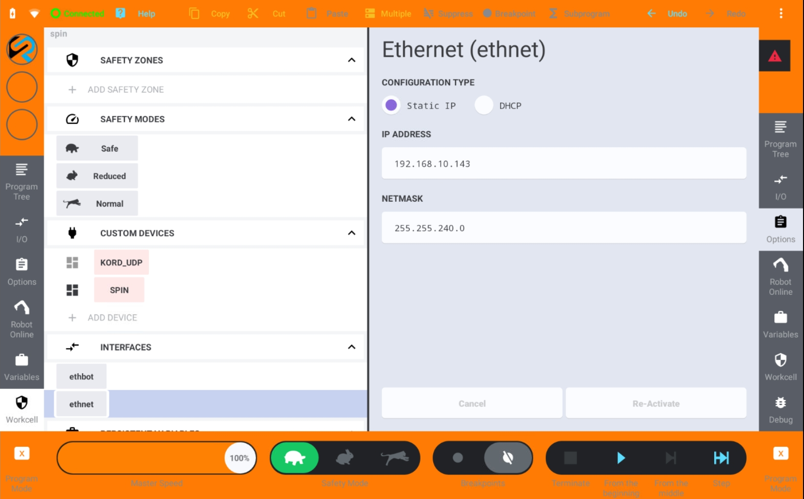
Through a switch, with DHCP. Select DHCP.
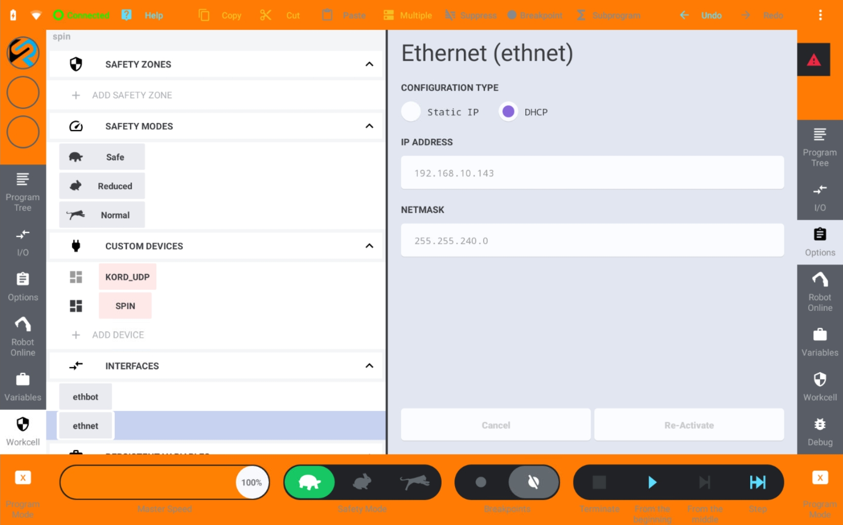
Nothing to set: the robot is connected over I/O, not over the network.
Connect to the Spin Bridge
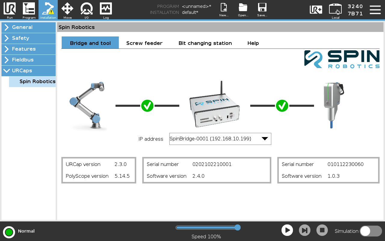
Open the URCap’s Bridge and Tool tab.
Choose the Spin Bridge from the list, or enter its address: 192.168.37.1 when the robot is connected directly to 2 Robot, otherwise the address of 1 Ext. network. The list finds Spin Bridges only on a network that supports multicast, which a direct connection does not.
Once connected, the tab shows the Spin Bridge’s serial number and software version, and those of the tool if one is connected. It warns if any of the versions are incompatible. The address is saved in the installation file.
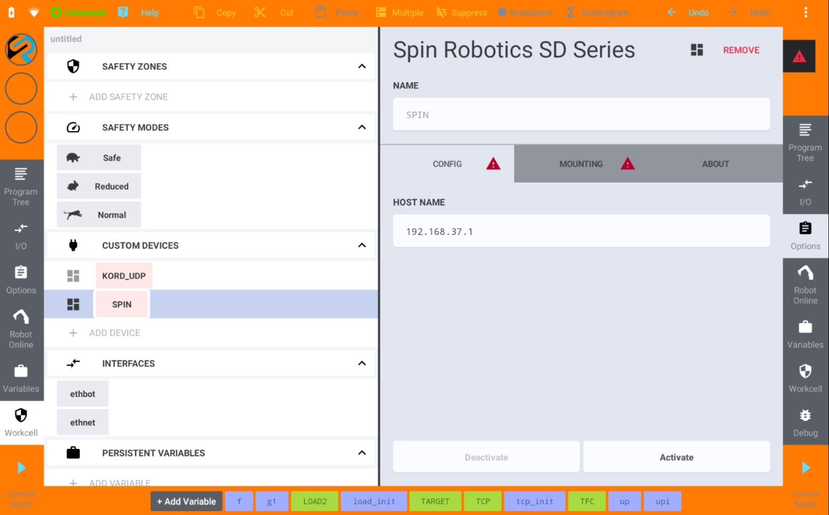
Select Workcell / Custom Devices / SPIN / Config.
In Host Name, keep the default, the address of 2 Robot, when the robot is connected directly to it. Otherwise enter the address of 1 Ext. network.
Press Activate.
Select Mounting and press Mount.
Note
On some robots, digital output 6 must be enabled, as it is used by the connection heartbeat. This output cannot be used for any other purpose.
Nothing to connect: the robot starts actions over the Spin Bridge’s inputs, and which input combination starts which action is set on the Spin Dashboard. See Dashboard.
Set the TCP and Payload
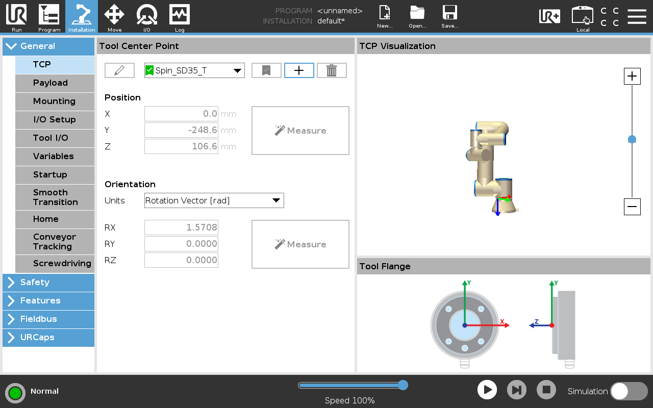
On Installation / General / TCP, select the tool from the list. The values it applies are listed in Position of Tool Center Point (TCP).
Note
The predefined TCPs are named for the older tools: Spin_SD35_T and Spin_SD70_T. Select Spin_SD70_T for every current tool, whatever its model. Spin_SD35_T is correct only for an older SD35.
On Installation / General / Payload, select the tool from the list.
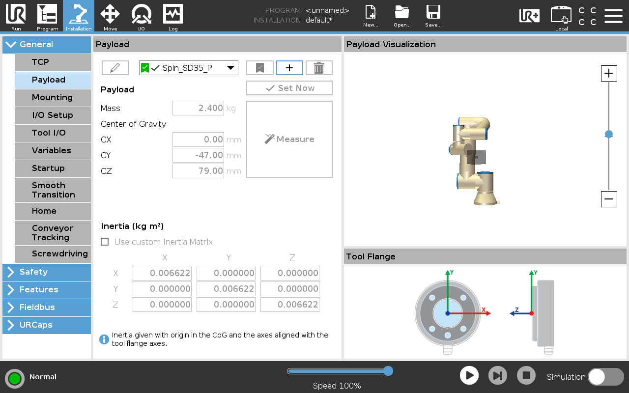
Both are saved in the installation file. A tool on a third-party tool changer, or a bit longer than the standard 50 mm, needs its TCP values altered to match.
Note
Leave Installation / General / Screwdriving unset. The URCap does not use the UR screwdriving function.
Under Variables / System Variables / TCP Frame, enter the position (X, Y, Z) and orientation (R, P, Y) below. The values are the same for every current tool.
Variable |
Value |
|---|---|
X |
0 mm |
Y |
-264 mm |
Z |
105 mm |
R |
90° |
P |
0° |
Y |
0° |
Older SD35 tools have a Y of -248.6 mm.
Position of Tool Center Point (TCP) states the same TCP relative to the robot tool flange, but gives its orientation as an axis-angle rotation rather than as roll, pitch and yaw.
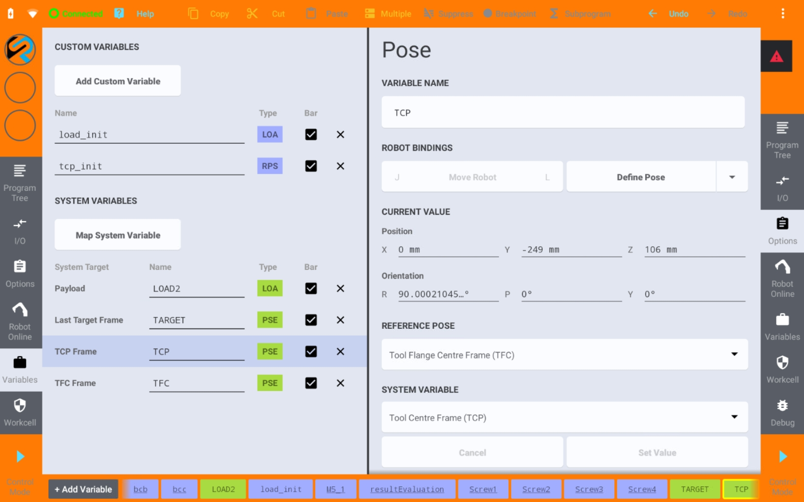
A tool on a third-party tool changer, or a bit longer than the standard 50 mm, needs its TCP values altered to match.
The payload of the tool is set automatically when the tool is mounted.
Set the TCP and the payload with the robot’s own procedure, using the values in Position of Tool Center Point (TCP) and Payload & Center of Mass (COG).
Map the Tool Buttons
On Installation / General / I/O Setup, map configurable input CI7 to freedrive and CI5 to the action the front button is to trigger. The mapping is saved in the installation file.
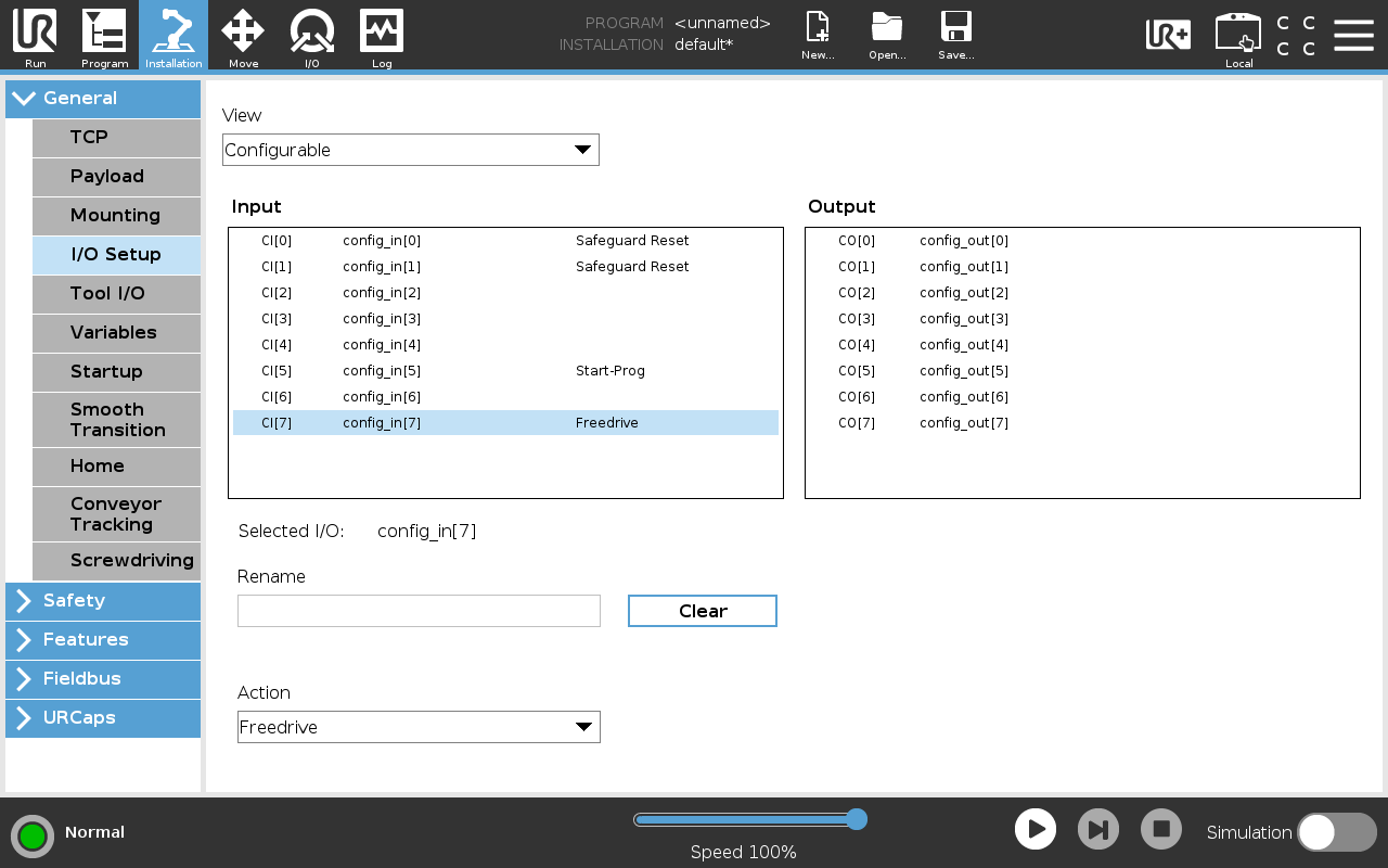
Nothing to map. Kassow robots are moved by hand by pressing and holding the backdrive button on the robot wrist or on the teach pendant. See Teaching a Position.
Set the robot input wired to the freedrive button to put the robot into freedrive, or its equivalent, with the robot’s own procedure. See Teaching a Position.