Mechanical Specifications
This section describes the mechanical dimensions and load limits of the SD/SDV-Series screwdriver tools.
All dimensions are given in mm [inch].
Note
All mechanical specifications are based on a standard configuration: safety shield installed, 50 mm screwdriver bit, no screw attached, and no additional accessories. Changes to the configuration (e.g., different bit length, vacuum tubing, or mounted accessories) will affect the TCP, payload, and center of gravity.
Tool Dimensions
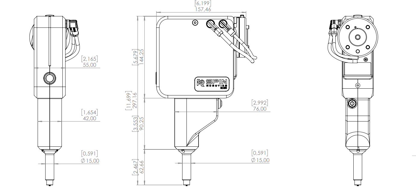
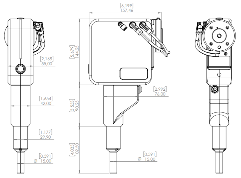
The SD/SDV-Series tool includes an integrated safety shield, which can move between two extreme positions.
Fully retracted safety shield
Fully extended safety shield
Notice
The total tool length varies depending on the position of the safety shield during operation. Ensure sufficient clearance in the robot workspace to avoid collisions in both positions. The full tool envelope must be considered when programming robot motion.
Integration Considerations
When integrating the SD/SDV-Series tool, consider:
Tool length variation due to safety shield movement
Clearance to surrounding equipment and fixtures
Screw length and accessibility
Cable routing and bend radius
Maximum Allowed Axial Load
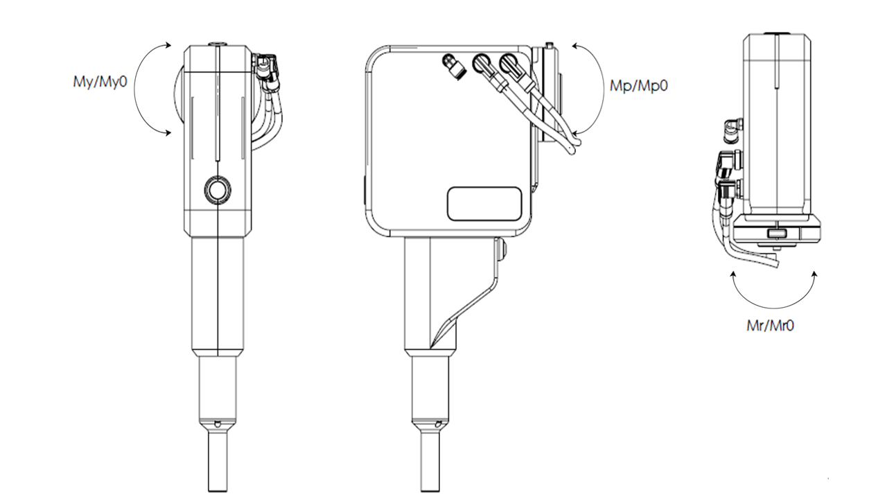
The maximum allowable loads at the robot flange are shown below.
These values must not be exceeded during operation.
Load |
Value |
|---|---|
Static moment Mr0 (Nm) |
95.6 |
Static moment Mp0 (Nm) |
56.4 |
Static moment My0 (Nm) |
56.4 |
Dynamic moment Mr (Nm) |
49.9 |
Dynamic moment Mp (Nm) |
29.4 |
Dynamic moment My (Nm) |
29.4 |
Notice
The limits apply to the complete tool assembly — screwdriver, safety shield, bit and screw, and any mounted accessories. Exceeding them reduces accuracy, shortens tool lifetime and may damage the tool. The robot payload, tool weight, and acceleration must be considered together to ensure that these limits are not exceeded. The integrator must validate the full system load.
Load Definitions
Mr / Mr0: Moment around the tool axis (rotation axis)
Mp / Mp0: Moment perpendicular to the tool axis (pitch)
My / My0: Moment perpendicular to the tool axis (yaw)
Static values (M0) apply when the system is not moving. Dynamic values apply during robot motion.