Spin Bridge Pinout
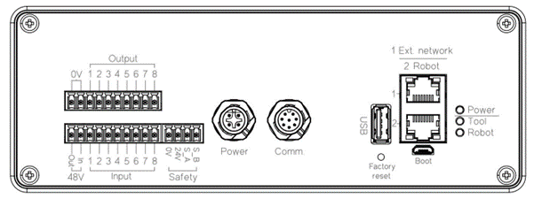
The Spin Bridge is the central interface between the SD/SDV-Series tool, the robot or PLC, and the safety system. All electrical connections to the tool are routed through it.
It provides the following electrical interfaces:
4-pin terminal socket for safety (OSSD + 24 V/0 V supply)
M12 power connector (48 V motor supply)
M12 communication connector (tool interface)
USB 2.0 host
2 × Ethernet ports (1: External network, 2: Robot connection)
Factory reset button
USB Micro (service port – do not use)
LED status indicators
Safety Terminal (OSSD Interface)
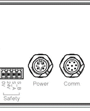
Safety terminal pinout
Pin |
Signal |
|---|---|
1 |
0 V (from robot / safety supply) |
2 |
+24 V (from robot / safety supply) |
3 |
S_b (OSSD channel B) |
4 |
S_a (OSSD channel A) |
The safety interface is powered externally by the robot or PLC. The OSSD signals are dual-channel, pulse-tested safety outputs.
Warning
The Spin Bridge provides safety-related signals but does not perform the safe stop function. The robot or PLC must monitor both OSSD channels and initiate a safe stop if either channel goes low. If it does not, the robot does not stop when the safety sensor triggers.
48 V Motor Supply Interface
The 48 V motor supply is generated and supplied by the Spin Bridge.
The internal power supply provides 48 V for the screwdriver motor
The supply is internally switched and forwarded to the tool
The 48 V circuit can be interrupted by internal control (software) or by an external safety relay wired into the I/O connector’s 48 V motor loop, which allows motor power to be removed as part of the safety system — see I/O module. Removing the 48 V supply fully de-energizes the motor.
Tool Communication Interface (M12)
The M12 communication connector provides:
RS485 communication
24 V supply for tool electronics
Internal routing of safety signals from the tool
Refer to Tool Pinout for detailed pin assignments.
Ethernet Interfaces
The Spin Bridge provides two RJ-45 Ethernet ports:
Port 1 – External network (service, configuration, OPC-UA)
Port 2 – Robot connection
USB Interfaces
The Spin Bridge includes:
USB Host (for external devices)
USB Micro (service interface - DO NOT USE)
Note
The USB Micro port is for service use only and must not be used during normal operation.
LED Indicators
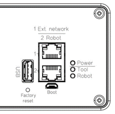
Status LEDs
LED |
Function |
|---|---|
Power |
Spin Bridge is powered |
Tool |
Tool is connected and communicating |
Robot |
Robot connection is active |
I/O Module
The I/O module enables control of the SD/SDV-Series without robot-specific software.
Note
Older Spin Bridge models do not include the I/O module.
Notice
Connecting the I/O module while the robot or Spin Bridge is powered can damage the equipment. Ensure that both are powered off before connecting it.
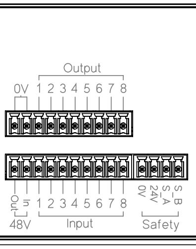
The I/O interface:
Complies with IEC 61131-2
Is galvanically isolated
Is powered externally via the safety connector (24 V / 0 V from robot)
I/O connector pinout
Pins |
Function |
|---|---|
1–2 |
0 V (robot 0 V, via the safety terminals – no wire needed) |
3–10 |
Outputs 1–8 (sourcing, 24 V from the robot supply) |
Pins |
Function |
|---|---|
1 |
48 V output |
2 |
48 V motor loop (break to disable motor supply) |
3–10 |
Inputs 1–8 (from robot) |
All I/O signals are referenced to the external 24 V/0 V supply provided by the robot or PLC. I/O functions are configured on the Spin Dashboard — see Dashboard.