Tool Pinout
This section describes the electrical pinout of the SD/SDV-Series tool connectors.
Two connectors are used:
8-pin M12 connector for communication, control, and safety signals
4-pin M12 connector for motor power (48 V)
8-Pin M12 Connector (Communication & Safety)
The 8-pin connector provides power for the tool electronics, RS485 communication, and safety signals.
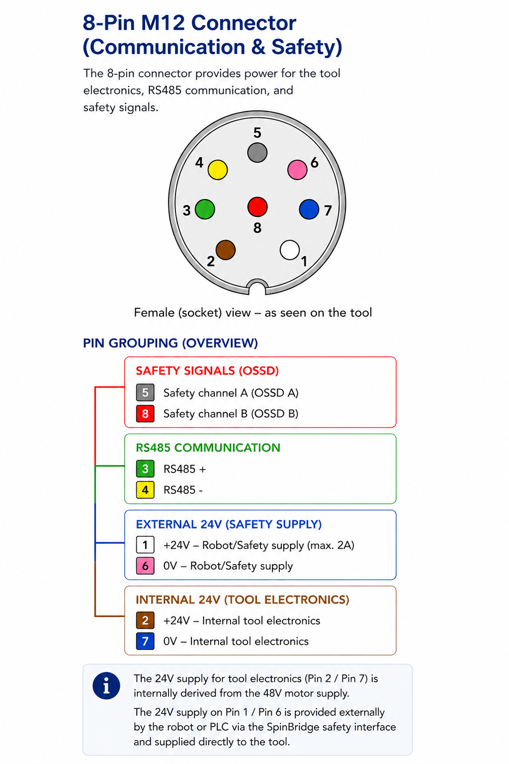
Communication connection pinout
Pin |
Color |
Signal |
|---|---|---|
1 |
White |
+24 V (external safety supply, max. 2 A) |
2 |
Brown |
+24 V (internal tool electronics, derived from 48 V) |
3 |
Green |
RS485 + (communication) |
4 |
Yellow |
RS485 - (communication) |
5 |
Gray |
OSSD A (safety channel A) |
6 |
Pink |
0 V (external safety supply return) |
7 |
Blue |
0 V (internal tool electronics) |
8 |
Red |
OSSD B (safety channel B) |
The 24 V supply for tool electronics (Pin 2 / Pin 7) is internally derived from the 48 V motor supply. The 24 V supply on Pin 1 / Pin 6 is provided externally by the robot or PLC via the Spin Bridge safety interface and supplied directly to the tool.
The communication cable must be shielded and used as specified; the cable shield contributes to EMC performance and signal stability.
4-Pin M12 Connector (Motor Power)
The 4-pin connector provides power for the screwdriver motor.
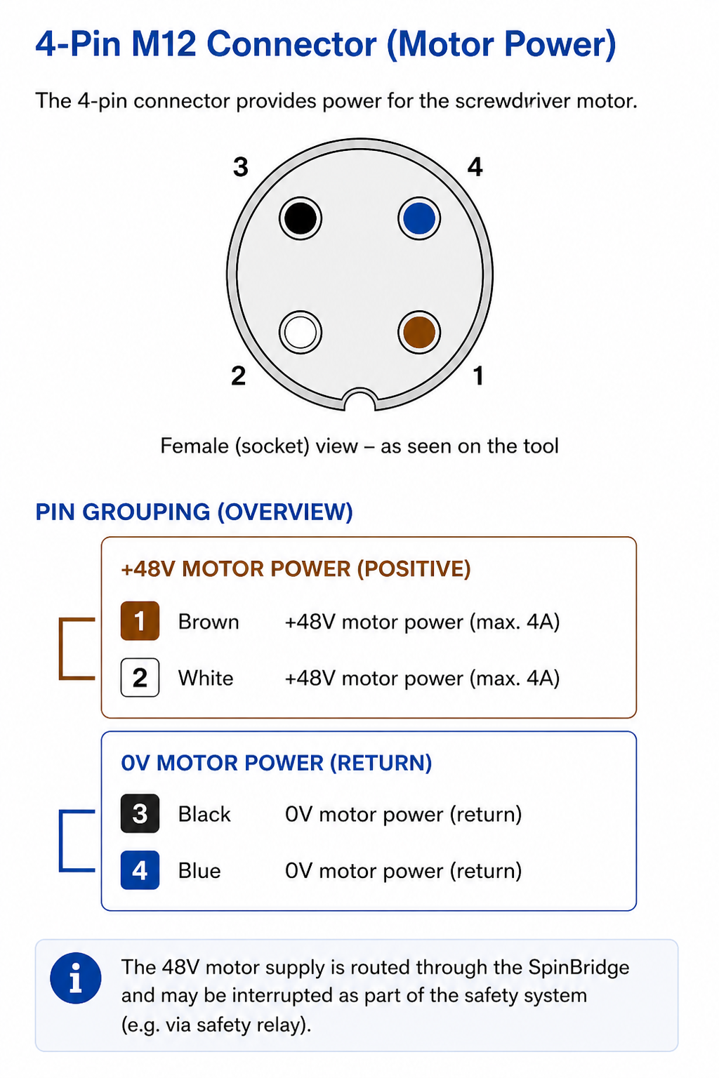
Power connection pinout
Pin |
Color |
Signal |
Description / Function |
|---|---|---|---|
1 |
Brown |
+48 V – Motor power (max. 4 A) |
Motor supply (positive) |
2 |
White |
+48 V – Motor power (max. 4 A) |
Motor supply (positive) |
3 |
Black |
0 V – Motor power |
Motor supply return |
4 |
Blue |
0 V – Motor power |
Motor supply return |
The motor supply must be properly connected and dimensioned according to system requirements. The 48 V supply is routed through the Spin Bridge and may be interrupted as part of the safety system, for example via a safety relay.